Graywire Lightning Cable Implant
CortexM7 CPU with USB HS + Wi-Fi Module + TaoGlass Micro Antenna + USB High Speed HUB + Micro SD Card + 2x USB Switch + Power Circuit + Crypto Chip
The Graywire cable is a unique piece of USB implant disguised as an USB charging cable, but with enhanced capabilities. A very small embedded system is contained within the USB connector head making the cable both a versatile and discrete USB programming platform. It could be either used as a general purpose implant targeting either the device connected to the lightning tip, or the host on the USB side. In this article, we are covering the case of an implant capable of taking control over an iPhone and streaming its video over WiFi, while allowing a remote computer to act as a keyboard + mouse combo. The implant is also recording the screen on a 128Gb SDCard
Demo
Graywire internals
Screen live streaming + remote mouse & keyboard
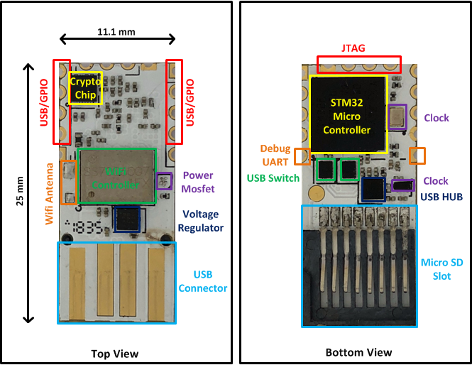
The USB implant features an ARM based SoC with:
- CortexM7 CPU with USB HS
- Wi-Fi Module
- TaoGlass Micro Antenna
- USB High Speed HUB
- Micro SD Card (128 GB storage)
- 2x USB Switch
- Power Circuit
- Crypto Chip
The Graywire cable hardware is reprogrammable and allows for a wide range of uses. For example:
Target/exploit
- It can target both sides: the phone or the computer
- A USB exploit can be packaged in the cable
Remote control
- Cable controlled remotely from the Wi-Fi connection
- Trigger the exploit from a distance
Specific use case: Screen capture & phone remote control
Hardware Description
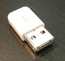
The Graywire cable looks like any charging cable but contains a very small implant hidden inside the USB connector.
Cable overview
Modified USB connector
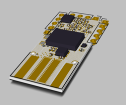
Components placement and routing has been optimized to fit in a very small form factor. The implant is small enough to be hidden into the USB connector.
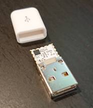
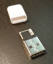

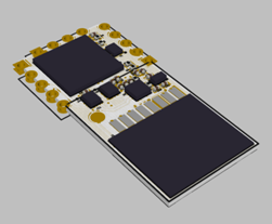
- Implant size: 25 mm x 11.1 mm x 2 mm
- Wi-Fi 2.4 GHz antenna: 5.9 x 4.1 x 0.24 mm (Ultra Low Profile Flex)
PCB technologies
- 0.6 mm PCB thickness
- 6 copper layers
- Via in pads
- Via filled
- Blind via
- Micro via
- 0.1 mm clearance
- 0.125 mm track width
- Impedance match for USB differential pairs
Implant details
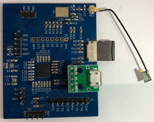
Development board
During the graywire cable development we created and used a custom development board. It features the same hardware components in a bigger form factor for easier development and testing.
- Dimensions: 62 mm x 50 mm x 10 mm
Architecture
The implant features 1 USB Hub and 2 USB Switches lay out as follows (see below picture). The Hub and Switches configuration are controlled by the microcontroller.
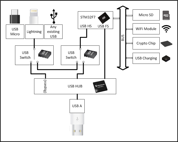
The architecture is based on a STM32F723 Cortex-M7 216 MHz microcontroller.
The STM32 can control the power of the Micro USB/Lightning (Phone charging).
It has 2 SDIO interfaces capable of communicating up to 48 MHz each. One is connected to the Micro SD, the other to a Murata WiFi module (based on Broadcom).
It is connected to a 3 ports USB Hub with an optional bypass as well as to 2 USB Switches allowing all possible configurations:
USB A (Host) direct (bypass) connection to USB Micro/Lightning
- Transparent / Idle
• USB A (Host) to a HUB connected to STM32 and USB Micro/Lightning
- Mass Storage Device to explore the SD Card from the Host
- Phone serial debug port
- Phone JTAG cable (SWD + UART + USB)
- Injection of payload to the host computer from STM32
• USB A (Host) connected to the HUB + USB Micro/Lightning (Host/Device) connected to STM32
- Emulating of Keyboard/Mouse to the device
- Emulating of HDMI cable to the device attached on Micro USB/Lightning
- Injection of payload to the attached device from STM32
- Any VID/PID can be set in the USB Hub, letting the Host (USB A) believe a specific device is attached.
Operating system
Drivers
The embedded STM32 microcontroller runs a port of Nuttx RTOS (Real Time Operating System), on top of which we added our own drivers and user land applications:
Standard OS drivers
- USB OTG High Speed driver
- SD Card FAT FS
- SDIO Wi-Fi
Custom drivers
- USB HID keyboard
- USB HID mouse
- iAP + Crypto
- SDQ
Development of new USB drivers is made easy thanks to the low level API, full control of the USB stack can be taken for specific usages (exploitation, injection of payloads, …).
Custom applications
- Graywire HDMI (For screen)
- Graywire HID (For remote mouse and keyboard)
- Low level commands (For dev/debug)
Standard OS applications
- Nuttx shell
- Init scripts (Wi-Fi network configuration or DHCP)
- Telnet server
Micro SD
The Micro SD card is auto mounted at boot, it contains Nuttx system files (Wi-Fi chip firmware, init scripts, configuration files), and provides a large storage space.
SD card details
- Filesystem: FAT32
- Mountpoint: /mnt/sdcard
- Capacity: 128 GB
The Micro SD card can be replaced when opening the USB connector.
Mass storage device
The Graywire cable can be switched into a mass storage device to explore the SD card content. This avoids opening the cable and physically removing the SD card.
Wi-Fi
At boot, the Graywire cable connects to a predefined Wi-Fi network and runs a DHCP client to get an IP address. The Telnet server listens on TCP port 23 and features a Nuttx Shell (NSH) for remote control. Telnet is the only service exposed externally.
Remote shell
Use case
Screen capture
To capture the phone screen as a video, the Graywire cable acts as an HDMI accessory.
HDMI Accessory
The Lightning DP1/DN1 lines are used as USB High Speed differential pairs D+/D-. They are connected to the High Speed USB PHY embedded in the Microcontroller STM32F723. The Graywire USB OTG driver running in Nuttx acts as a USB device and presents the following USB interface and endpoints to the USB host (phone):
 1Interface Descriptor:
 2      bLength                 9
 3      bDescriptorType         4
 4      bInterfaceNumber        1
 5      bAlternateSetting       0
 6      bNumEndpoints           2
 7      bInterfaceClass       255 Vendor Specific Class
 8      bInterfaceSubClass     42
 9      bInterfaceProtocol    255
10      iInterface              7 Nero
11      Endpoint Descriptor:
12        bLength                 7
13        bDescriptorType         5
14        bEndpointAddress     0x85  EP 5 IN
15        bmAttributes            2
16          Transfer Type            Bulk
17          Synch Type               None
18          Usage Type               Data
19        wMaxPacketSize     0x0200  1x 512 bytes
20        bInterval              10
21      Endpoint Descriptor:
22        bLength                 7
23        bDescriptorType         5
24        bEndpointAddress     0x04  EP 4 OUT
25        bmAttributes            2
26          Transfer Type            Bulk
27          Synch Type               None
28          Usage Type               Data
29        wMaxPacketSize     0x0200  1x 512 bytes
30        bInterval              10
These endpoints are recognized by the phone as part of an HDMI accessory. As such, the phone uses them to send screen frames. The protocol has been reversed engineered and re-implemented within a Nuttx user land application (Graywire daemon).
Protocol details
The screen video feed is encoded by the phone in H.264 format and encapsulated within so called SDAT frames. These frames are decoded by the Graywire application and stored on the SD card.

Screen recording on SD
Video files are named using the current system date and time. System date / time is obtained from the phone using iAP. (Optionally, it is possible to obtain date / time via NTP).
1nsh> ls -l /mnt/sdcard/graywire
2/mnt/sdcard/graywire:
3 -rw-rw-rw-  226354 20181020-185800.bin
4 -rw-rw-rw- 6624844 20181020-185802.bin
5 -rw-rw-rw- 1206313 20181020-190001.bin
6 -rw-rw-rw- 1058616 20181020-190101.bin
7 -rw-rw-rw-      32 20181020-191309.bin
Live streaming
Additionally to being stored on the SD, H.264 frames are streamed via Wi-Fi. The remote controller PC can view the phone screen in realtime, and optionally interact with it (See Remote mouse & keyboard).
Remote mouse & keyboard
Additionally to HDMI accessory endpoints, HID (Human Interface Device) endpoints are presented to the host phone. A user land application forwards HID inputs received from a TCP connection. This means the USB Mouse and Keyboard can be controlled remotely from the Wi-Fi connection.
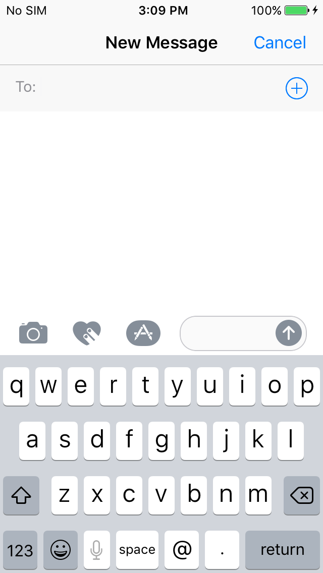
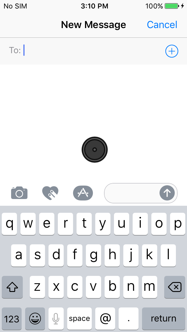
AssistiveTouch:
To activate the Mouse, a special command is sent over iAP to enable AssistiveTouch. This makes the mouse cursor appear on the phone screen. Any movement performed on the controller laptop is transferred through TCP and replicated by the Graywire USB HID endpoint, resulting in a cursor movement on the phone screen. After use the Mouse is disabled by sending a disable AssistiveTouch command over iAP.
Mouse
1Interface Descriptor:
2      bLength                 9
3      bDescriptorType         4
4      bInterfaceNumber        0
5      bAlternateSetting       0
6      bNumEndpoints           1
7      bInterfaceClass         3 Human Interface Device
8      bInterfaceSubClass      1 Boot Interface Subclass
9      bInterfaceProtocol      2 Mouse
AssistiveTouch Mouse disabled / enabled
Keyboard
1Interface Descriptor:
2      bLength                 9
3      bDescriptorType         4
4      bInterfaceNumber        0
5      bAlternateSetting       0
6      bNumEndpoints           1
7      bInterfaceClass         3 Human Interface Device
8      bInterfaceSubClass      1 Boot Interface Subclass
9      bInterfaceProtocol      1 Keyboard
Remote Keyboard disabled / enabled
When the USB keyboard endpoint is active, the virtual keyboard disappears from the screen.